Facial Surface Identification
1. Face Recognition
- Automatic recognition for access control (no access card, no PIN code)
- Well accepted by users (in comparison with other biometric means)
- With cooperative scenario (people want to be recognised)
- But face sensitive to illumination and point of view
2. Motivations for 3D Face Recognition
- Success of profile recognition
- Robust against point of view (3D)
- Robust against illumination changes, makeup
- Static information (forehead, chin, nose, cheeks)
- Complementary to color information
- Real dimension (no scale factor)
- Easy background removal
- Not fooled by a photo
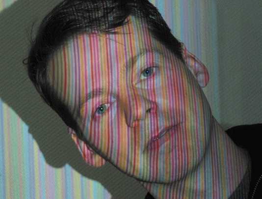
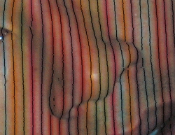
3. 3D Acquisition with structured light
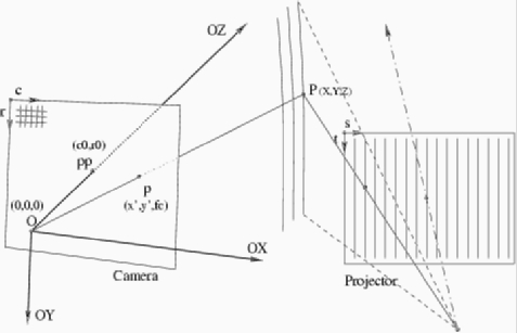
3.1. Structured light
- 1 Projector and 1 camera: triangulation
- Camera (x',y') + Projected stripe label 's' at (x',y') -> P (X,Y,Z)
- Low cost
- Fast (each image gives a 3D surface)
- Real distance measures
3.2. Setup
- Sitting attitude (less variation in position)
- Diagonal striping (against eyebrow and mouth problems)
- Working distance around 1 m
- Volume of capture 40 x 30 cm, 30 cm depth of field
3.3. Prototype A (M2VTS project - 1998)
- Black and White CCD analog camera (Panasonic WV-BL600)
- 150 W projector with fan cooler

3.4. Prototype B (BIOMET project - 2002)
- Colour digital camera (Canon G2) controlled through USB
- Flash for instantaneous (no blur) and powerful (depth of field) illumination
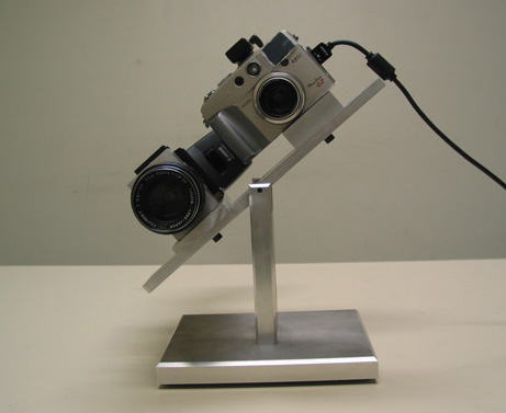
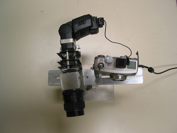
- Colour slide for projection
 (Part of slide)
3.5. Calibration (Proto B)
- Objective: obtain 3D measures as accurate as possible through the
optimisation of system parameters
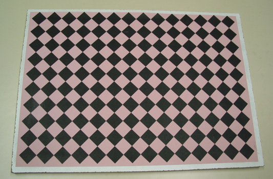
- Use a calibration object (here a plane with squares) of known geometry
3.5.1 Calibration object
- Planar object with printed squares
- Reference points are corners
- Diagonal print to reduce interference with stripes projected nearly
vertically
3.5.2 Reference point localisation and indexing
- Corner localisation: intersection of square borders
- Stripe indexing: localisation and colour of projected stripes around
corners
- Global consistency: position and stripe index of corners should follow a
rather linear law
3.5.3 Parameter estimation
- Objective: Adapt parameters to minimise the error between reference points
detected in images and the projection of corresponding points of the
reference object
- Parameters: camera intrinsic, rotation/translation and
camera/projector arrangement
- Step 1: camera calibration: optimise camera intrinsic (focal length,
principal point and distortion coefficients) and extrinsic parameters
(rotation / translation). Derive refined point positions in the reference
object (Lavest's approach)
- Step 2: system calibration: estimate the planes corresponding to the
projected stripes from the knowledge of point positions obtained by step 1
3.5.4 Results
- Average errors less than 1 mm have been obtained for objects placed at 1 m
distance
3.6. Surface capture (Proto B)
- Detection of stripe centres
- Stripe property: Colour (Red, Yellow, Green, Cyan, Blue, Magenta)
- Stripe label: 3 successive colour stripes allow to derive stripe index
- Image (x, y, stripe label) => 3D (X, Y, Z)
3.7. Database
- Coming soon, through ELDA (European Language Distribution Agency)
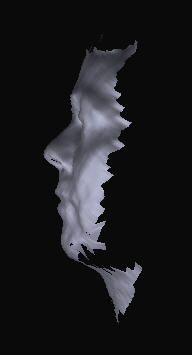
4. Facial Surface Analysis
4.1 Surface matching
- 3 rotation and 3 translation parameters must be tuned to match 2 surfaces
(no scale)
- We extract and match 2D profiles obtained by parallel planar cuts (1cm
apart) of facial surfaces
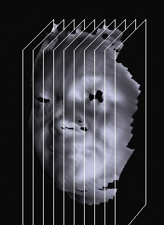
4.1.1 Nose localisation thanks to nose prominence
- rough estimation of 3 translation parameters
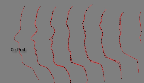
4.1.2 Normalisation thanks to facial symmetry
- Parallel profiles (planar cuts) matched by tuning 3 parameters (2 rotation and 1 translation)
- Figure shows homologue 2D profiles when brought
into correspondence
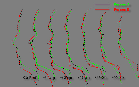
4.1.3 Surface comparison by 2D profile matching
- Remaining 1 rotation and 2 translation parameters are fine tuned to match
2 surfaces
- Each pair of corresponding profiles gives a distance (area between curves
/ arc length)
- The sum (without outliers) of distances between corresponding profiles is
the matching score
4.2 Grey Matching
4.2.1 Measuring grey levels
-
Grey levels are obtained from the striped image (captured
for 3D), along the profiles (4.1)
-
Grey values on stripes are corrected, knowing the position
and color of the stripes
-
To robustify information, grey values in the vicinity of the
profiles are integrated
-
Grey measures are differences along the profiles to
reduce illumination influence
4.2.2 Comparing grey measures
-
Corresponding curves of grey measures are compared
-
One shift parameter must be solved (geometric correction was
done in 4.1)
-
Each profile pair gives a grey difference equal to the mean
distance between grey curves
-
The grey comparison score is the sum of each profile grey
difference
4.3 Face Comparison
-
Two faces are compared relatively to geometric and
radiometric (grey) information
-
First, the 3D surfaces are matched (see 4.1), leading to a
geometrical score (in mm)
-
Secondly, grey distances are measured (4.2) along the
profiles retained for 3D matching
-
Both geometric and grey scores are compared to statistics to
conclude about the face similarity
-
Geometric and grey statistics are collected from supervised
tests (same/different persons)
5. Results
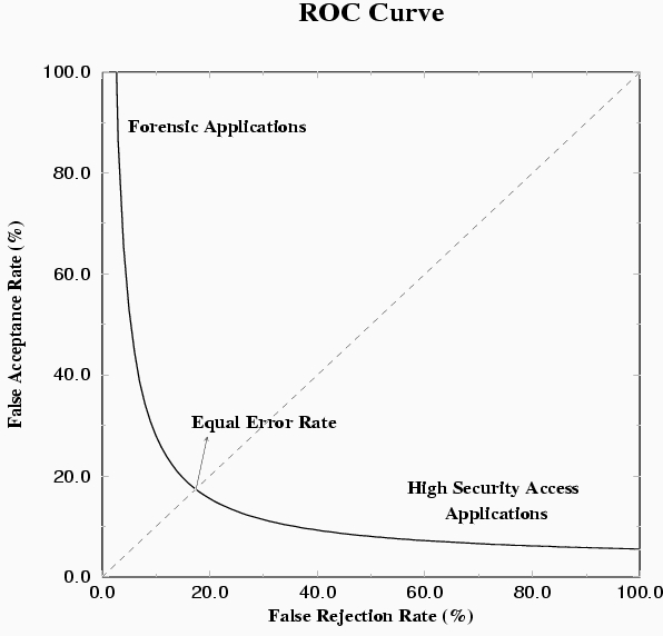
5.1 Definitions
-
False Acceptance (FA): an impostor is accepted by the system
-
False Rejection (FR): an acceptable client is rejected by
the system
-
Low FA and low FR are competing objectives depicted by a
"ROC curve"
-
For the operational point FA rate = FR rate, we have the
Equal Error Rate (EER).
5.2 Results
-
Several tests have been performed on 2 databases with
different quality
-
Surface matching is accurate and achieved 4 % EER
-
Grey matching achieved 8 % EER
-
Fusion of surface and grey resulted in 1 % EER
5.3 Discussion
In the tests, errors originated from
-
Automatic 3D surface capture (mainly in nose, eyes,
eyebrows, beard)
-
Surface matching due to local minima and bad capture
-
Grey matching due to illumination influence
6. References
The interested reader should refer to my Homepage, Publications to find
published papers related to this research.